Modeling Tips
Learned the hard way
How to install a DCC decoder
Coming upBuild a RLW K-27 kit
See this blog post.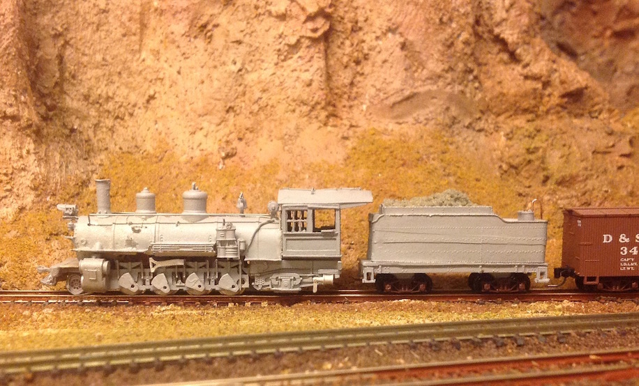
How to make a Digitrax dwarf signal
Using the Base Mast Kit (Digitrax artikel SMBK, N scale) as - well - the base - we add the typical Rio Grande hood from styrene. If desired, cut off the upper head just above the lower head (Secret tip: you can make a dwarf from this stump by soldering it to a copper tube for ground + a wire to each LED). See [this blog post](/blog/2019/rio-grande-signal/).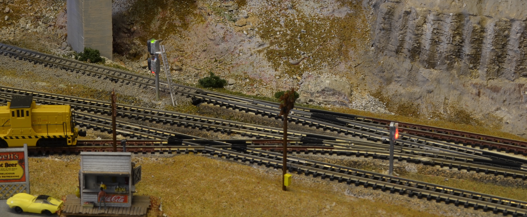
Build a housing for the Digitrax DS52 stationary decoder
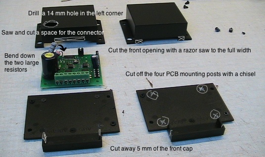
The Digitrax DS52 stationary decoder consists of a PCB with a connector. After programming, it seemed wise to put it inside a decent enclosure to reduce dust and accidental damage. At Conrad I ordered a 53,5 x 45 x 23 mm StrapuBox item 522600. Pictured below are the modifications to get the decoder inside. Put a label on the front with the decoder ID (I use pattern DS52-###) plus the DCC adresses of both outputs and attach the case to the layout with 2 screws.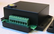
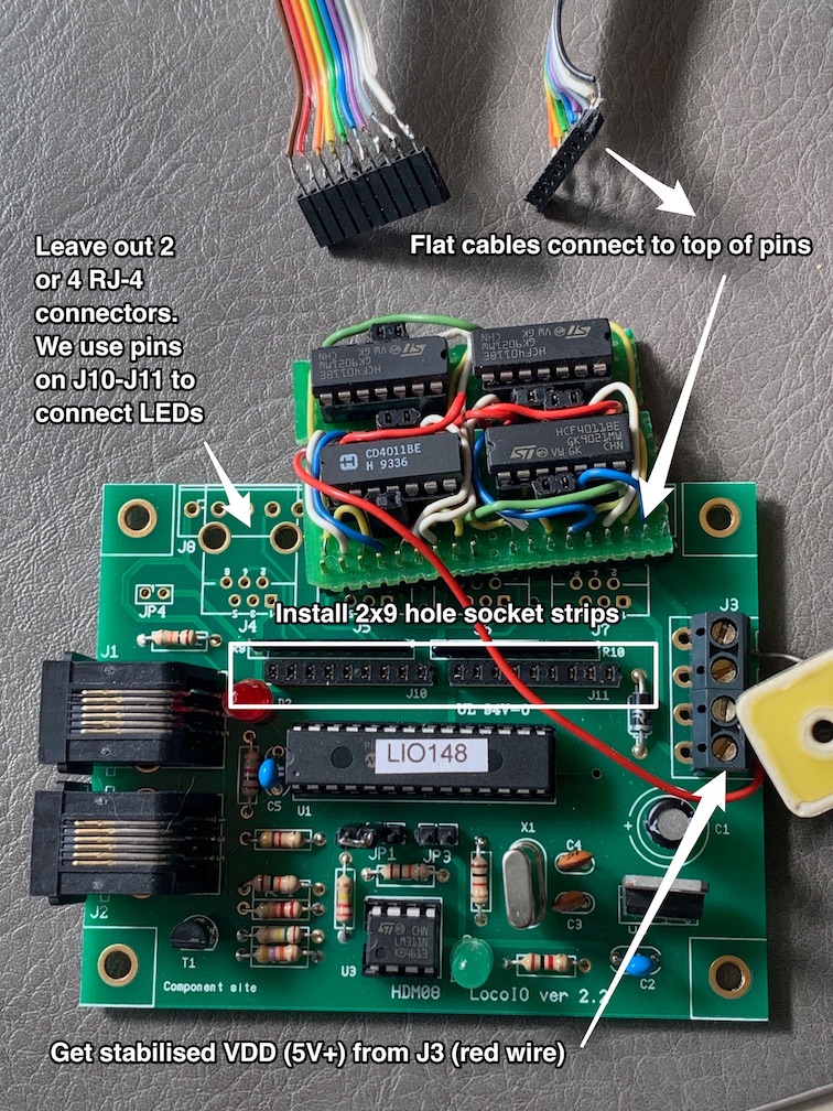
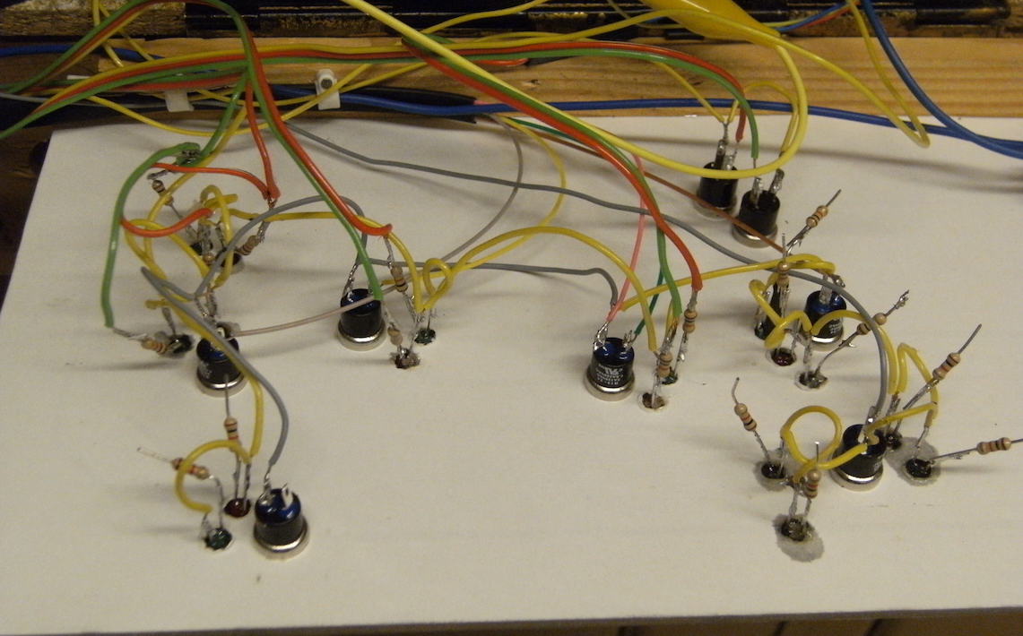
Build an add-on logic inverter daughterboard for an HDL LocoIO
JMRI Panel
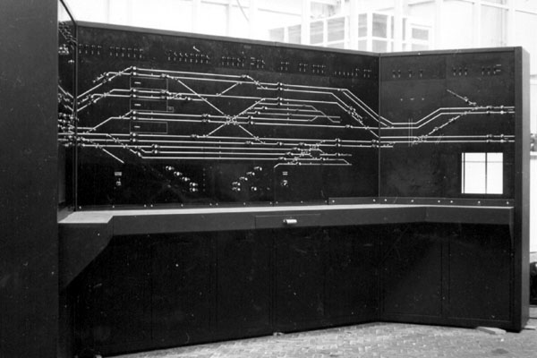
My digital control panel was built using Panel Editor and is displayed on a compact LCD monitor by JMRI PanelPro 2.4.1 on OSX 10.4.6, the last version supported by my MacMini hardware/Java combo.The graphics match a generic (US-built) Entrance-Exit (NX) CTC machine, in use from 1950 until the mid-nineties. However, most turnouts are operated with an Individual Function Switch (IFS); see the Signaling Wiki.
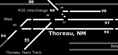
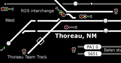
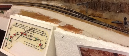
Some years later, signals were added on the layout as well as to the panel. All the logic to show the correct Aspects is controlled as Signal Mast Logic following a customized Rio Grande 1965 Rule Book signal definition. My physical control panels on the layout fascia sport the same graphic style, be it black on yellow to match the carpet:
Back to Railroading/Layout