DCC
Digital Command Control

What is Digital Command Control?
Starting in the spring of 2004, I have switched to Digtrax DCC with a Zephyr command station. 10 Years ago, Märklin and Lenz started with DCC, but it was too expensive for me. I did build an electronic occupancy detector (works like a dream as of 2006, connected to the inputs of a LocoIO, by the way) and read all the manuals, but never bought any hardware. The regular DCC summaries in Model Railroader kept me informed on the latest developments, and later on the internet made this even easier. So in 2004 I ordered a DCC-stater pack from the USA.
Digitrax Zephyr
What attracted me in Digitrax were the price of the starter set and the elegance of the Loconet network system, that connected all signaling devices. Lenz also had an interface between DCC and a computer, but after the first edition for Macintosh there was no follow up and I gave up on that too.
JMRI
![]()
In 2003 I learned that JMRI was developed as platform independent, Java based software for controlling a DCC layout. Between JMRI - which I tested on Mac OS 9.2 - and ™LocoNet, there was a thing called LocoBuffer, that you could build yourself following the design by J. Jabour. Just as my Zephyr system arrived in the mail, the website on LocoBuffer disappeared from the web. After extensive browsing and reading, I learned that a company had develeoped a commercial follow up, christened the LocoBuffer-II. When I sent them an email asking for the conditions of overseas shipment, I was told that the European distributor was Rob Heikens, living just 60 kilometers away. Just before the summer holidays of 2004 I ordered this hardware interface, dragged one computer to the third floor and started up JMRI: It all worked perfectly and it was frightening to see an engine start and stop without physically touching the layout controls.
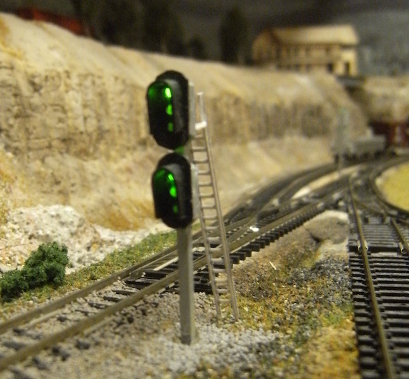
Signaling is also handled by JMRI Signal Masts since Winter 2013, with a Digitrax SE8c board and Signal Mast Base kits, dressed like Rio Grande signals with their distinct Darth Vader hoods.
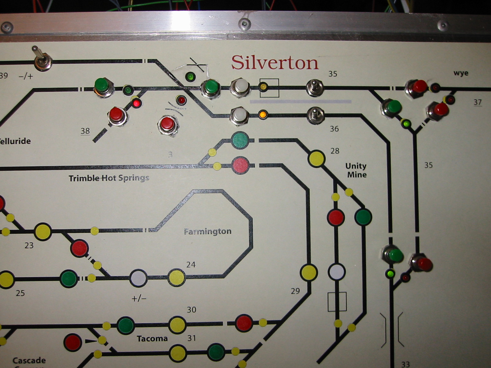
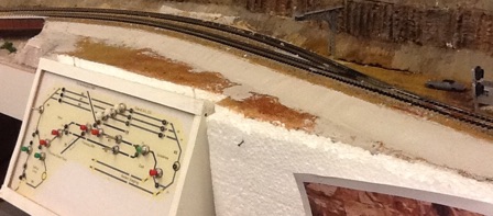
Panels along the layout are connected to JMRI and show occupancy of blocks, turnout positions as well as receive input to change them (more on JMRI PanelPro).
Wiring
I tried a mixed DCC/conventional DC wiring scheme. hoping to manage the switches via Loconet whilst running the engines on either a DCC or regular DC throttle. It gave me some time to put a decoder in the engines that have enough room for one. But 10 years in I changed to full DCC as keeping one system running already is daunting enough. Even the Atlas (Tomix) track cleaning car - with vacuum cleaner! - had room for a TCS decoder, and a flashing light on top.
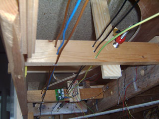
Although it doesn’t make wiring as simple as DCC can be, I decided to run 7 bus wires around the whole layout:
- permanent DCC - for driving stationary decoders
- switched DCC/DC/off - for feeders to the tracks, with a switch on the panel for every one of 4 districts
- a common return wire for wires 1-2
- 6 Volts DC - for electronic circuits and non-DCC occupancy detectors
- 12 Volts auxiliary power - for all devices except DS54 stationary decoders (see note)
- 23 Volts capacitive discharge current - for hitting those Peco switch motors and double turnouts
- a common return wire for wires 4-6
I used standard home wiring (2,5 mm2/AWG 12) for the bus. It’s cheap and prevents voltage drop along the length of the pike, which may be tiny compared the the average american N scale layout, but is big enough to spend another 10 years on building and enjoying.
Third Party DCC Links
- Wiring the Digitrax DS54, be sure to keep it apart from the other loconet devices (read why in this excellent contribution by Bob Jacobson of JMRI fame)
- LocoIO by Hans Deloof