RLW Nn3 K-27
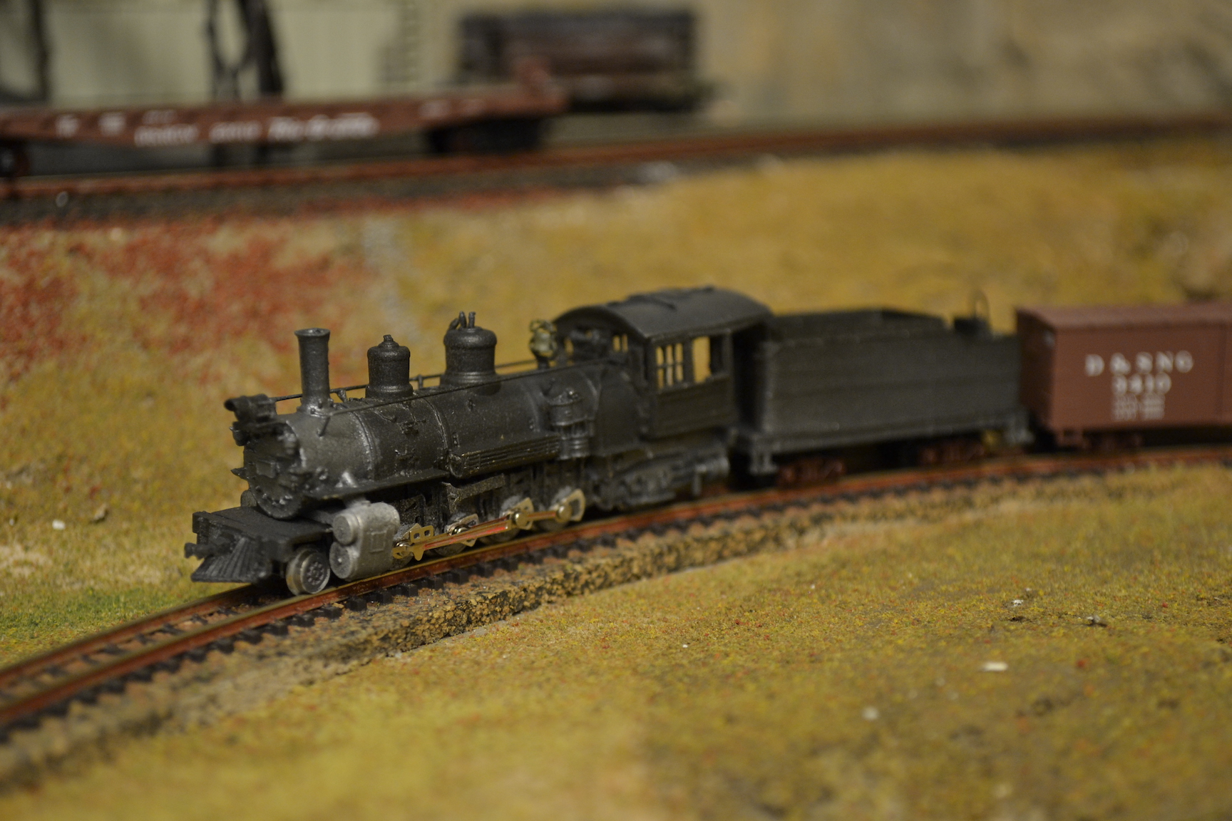
I had this RLW kit waiting for a couple of years. Finally, the time came to build it.
As the pictures in my kit instructions were not printed too clearly, I wrote this addendum to provide some extra information to fellow model builders. As long as you study the instruction sheet in advance, regularly compare it to your parts and work in small steps, wear extra visors if needed, this can be a great kit to build.
Prepare by searching for extra pictures of the engine you wish to model, either online or in your Rio Grande books.
Boiler
Take care when you handle the boiler casting, as the handrail supports tend to break after bending 3 times.
File and fit the fire box onto the rear of the Märklin frame, so it matches the dimensions provided in the instruction sheet, but do not affix it yet.

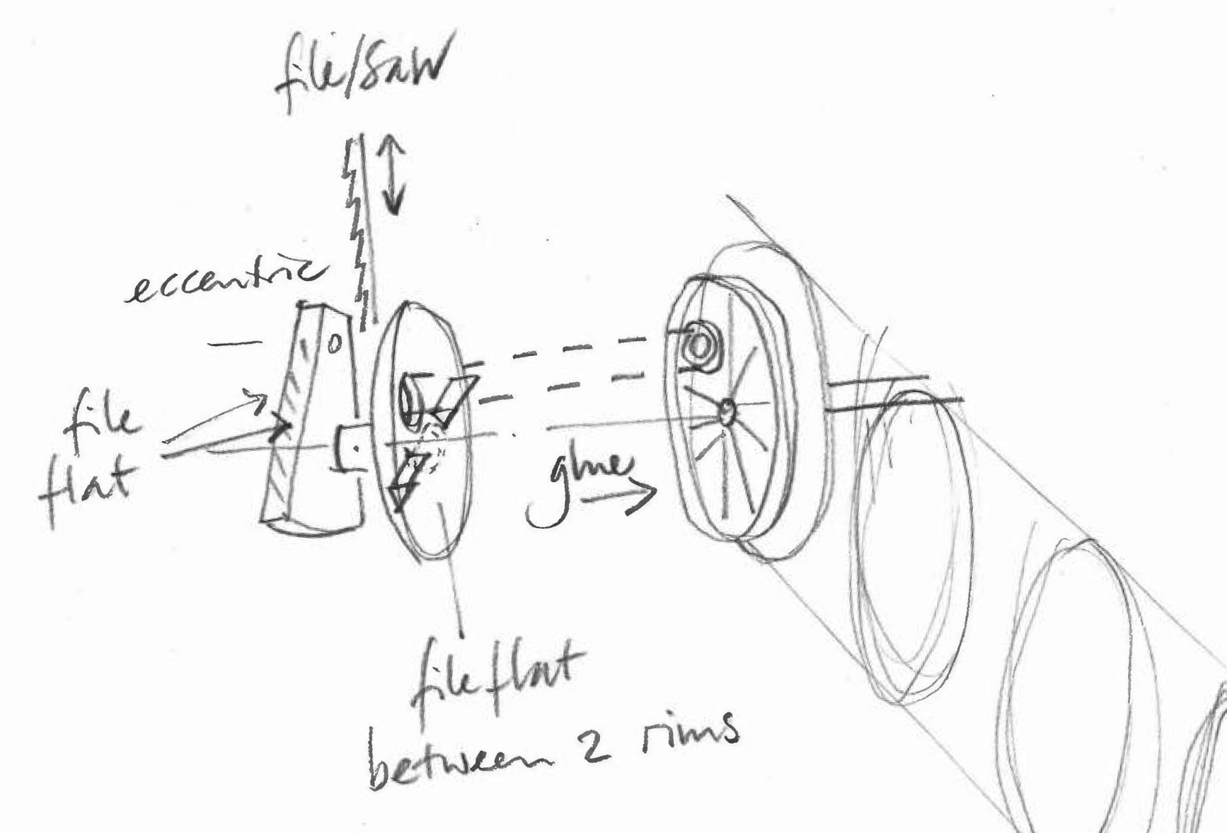
As stated in the instructions, getting the drivers operating is the heart of the kit assembly. I found just 9 eccentric wheel castings in my kit, one of which was not entirely circular. After carefully straightening each casting, file the sides and top of the outside counterweights. Next, using a fine metal thin sabre saw blade, clear the centric connection axle between the wheel cover and the counterweight. Try to get it centered or the suspension plate will wobble. Drill the hole in the wheel cover to fit over the side rod connecting hole on the Märklin driver wheels. Be careful not to damage the smaller holes in the counterweight. File flat the back of the wheel caps, leaving only the 2 opposed small rims to it between the red plastic wheel spokes. Start on one side by gluing each of the 4 wheel covers to the Märklin drivers using CA glue, starting at the far side. Using your finger nails press each wheel cover flat against the driver wheel before the glue sets. Inspect how good you succeeded in keeping the axles centered by turning the four axles while watching the axles behind the counterweights from the top. Continue to shave small amounts off the eccentric side of these axles. I used a small modeler’s saw blade that will fit between the wheels and needs no extra pressure except slightly flexing the blade from the end you’re holding. Keep turning the wheel while filing and check you create a round axle cross-section, not one with flat sides.
Frame suspension
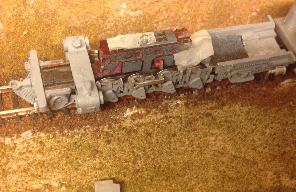
Following the instructions, file flat the inside of both frame suspension castings, but first check the drawings to prevent you end up with two right side frames. In fact these castings are asymmetric, with the end that has a hole in it pointing to the rear up against the fire box. Flatten the castings by lying it flat on a fine file doing the final sanding of the back. Using a low speed Dremel sanding disc, square the slots that go over the wheel axles. Fit on the Märklin frame and try to turn the wheels. Either remove more eccentricity from the connecting axles or slightly widen one side of a slot to allow free movement of all four drivers inside the suspension frame casting. As the sides will rest on the axles, leave some room around a wobbly axle or the frame will always move up and down. Less is more!
In front, the suspension frame castings are supposed to fit between the cylinder casting. Remove some metal from the inside of the cylinder casting to allow the frame halves to freely sit over the driver wheels. In the rear, carefully file a small 1x1 mm notch to fit the frame sides under the fire box. Once the suspension frame plates fit over the drivers, glue the two Walschaert Y-shapes to the outside over the second driver with the forked side pointing to the front.

Märklin frame and adapter trucks
The pilot and trailing trucks on my Märklin item #8896 Z scale engine are metal castings. Remove both trucks from the frame (remove the screws one at a time will keep the gear cover and drivers in place on the frame). Lift off the steel plate and snip off the point with 1 hole. On the casting, cut away the coupler pin and protrusion. File 1.5 mm off the top of the truck to come level with the top of the mounting eye and have the truck clear the firebox.
Tender
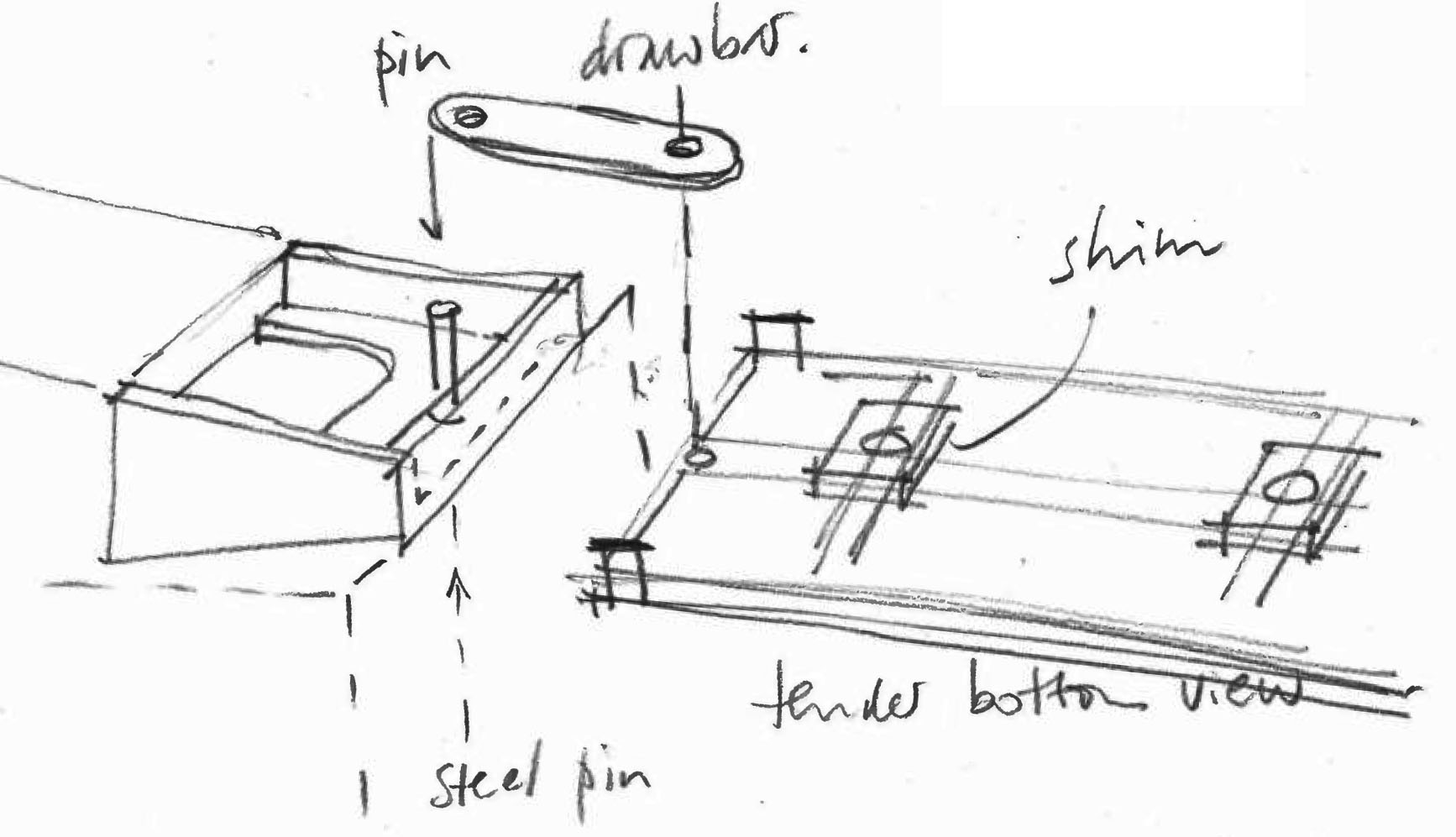
Add two 1 mm thick styrene shims between the tender trucks and the sub frame to clear the wheels and get the rear coupler at the correct height. Drill a hole to attach a connection bar between the tender and the engine. Also attach a small pin below the bottom of the firebox/engine cabin (eg. a thin tube pointing down, affixed with a small bolt from above).

Left over parts
I could not discover where to use the 2 semicircular 3 mm wide steps/boxes.


Enjoy Reading This Article?
Here are some articles you might like to read next: